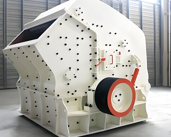
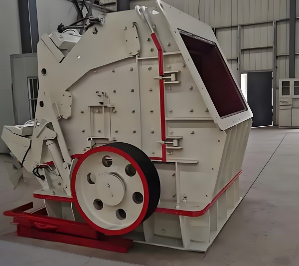
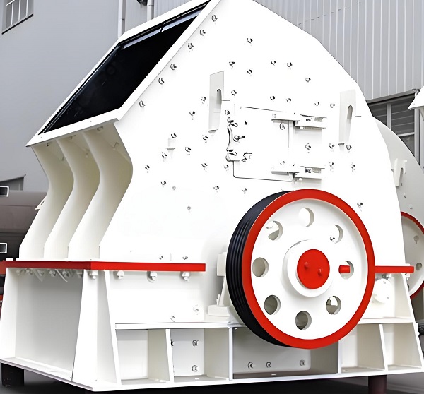
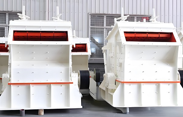
Impact crushers, as core crushing equipment in mining, building materials, and other industries, are subject to constant high-load, high-impact operating environments. They are prone to failures due to factors such as component wear, improper operation, and untimely maintenance, impacting production efficiency. Mastering the identification, cause analysis, and repair techniques for common equipment failures is crucial to ensuring continuous and stable operation. This article systematically examines common impact crusher failures from the perspective of core components and overall operation, providing detailed repair solutions and preventative strategies, and offering practical guidance to industry practitioners.
Core Component Failures: Identification, Causes, and Repair

1. Blow Bar Failures: Wear, Breakage, and Detachment
The blow bar is the core component of the impact crusher that directly impacts the material and is a common failure site. Common problems include excessive wear, breakage, and detachment, all of which lead to a significant decrease in crushing efficiency and uneven output particle size. Excessive blow bar wear primarily stems from two factors: First, material hardness exceeds the equipment's tolerance. For example, using a blow bar designed for limestone to crush hard rocks like granite will accelerate blow bar surface wear. Second, improper blow bar material selection—failure to use wear-resistant materials such as high-chromium alloy or high-manganese steel, or substandard heat treatment—can shorten its service life. Third, excessive material retention in the crushing chamber causes prolonged and repeated friction between the blow bar and the material, rather than normal impact crushing, exacerbating wear. Blow bar breakage is often caused by excessive impact loads. For example, if hard foreign objects like iron or steel are mixed into the feed, the high-speed rotating blow bar will instantly exert excessive force upon impact, leading to brittle fracture. Furthermore, uneven blow bar installation clearances and unbalanced forces during operation can also cause localized stress concentration fractures. Blow bar detachment is often related to installation procedures. For example, loose wedges or improperly tightened bolts to the specified torque can easily cause the blow bar to fall off the rotor under the vibration and impact of the high-speed rotation of the equipment. Repairs for the above-mentioned faults should be handled on a case-by-case basis. If the blow bar wear does not exceed the design limit (usually, replacement is required when wear reaches 1/3 of its original thickness), the service life can be extended by adjusting the blow bar position (e.g., turning the less severely worn side toward the crushing surface). If the wear is severe or broken, the entire blow bar must be replaced. When replacing, please note: Select blow bars made of wear-resistant material that matches the original model. Clean impurities from the rotor mounting surface before installation. Use a torque wrench to tighten the wedges or bolts to the specified torque to ensure a tight fit and uniform clearance between the blow bar and the rotor. For blow bar detachment, first inspect the mounting components (wedges, bolts, and locating pins) for damage. If any components are deformed or worn, they must be replaced. After installation, manually rotate the rotor to confirm that the blow bar is not loose or stuck before starting the machine.
The key to preventing blow bar failures lies in: strictly controlling the hardness and particle size of the feed material to avoid the intrusion of hard foreign matter; regularly inspecting blow bar wear, maintaining a wear log, and replacing consumable parts according to schedule; and selecting high-quality blow bars from reputable manufacturers to ensure that the material and workmanship meet standards.
2. Rotor Failure: Excessive Vibration, Bearing Overheating
The rotor is the core component that drives the blow bars. Failures primarily manifest as severe operating vibration and bearing overheating. If not addressed promptly, these can lead to chain reactions such as frame deformation and damage to the transmission system.
The causes of excessive rotor vibration are complex: First, rotor imbalance, such as uneven blow bar wear (severe wear on one side) or excessive material debris adhering to the rotor, can shift the rotor's center of gravity and generate centrifugal vibration during high-speed rotation. Second, rotor shaft bending, often caused by long-term overload operation or severe impact from foreign objects, resulting in excessive bending moment and deformation. Third, excessive bearing clearance or damage. Bearing wear can cause radial and axial clearances to exceed allowable limits, reducing rotor stability and causing vibration. Bearing overheating is primarily caused by: poor lubrication, such as insufficient lubricant, an inappropriate lubricant type (e.g., using regular butter instead of high-temperature grease), lubricant deterioration and agglomeration, which increase bearing friction and heat accumulation; improper bearing installation, such as overtightening or loosening the inner ring and shaft, or the outer ring and bearing seat, which creates excessive friction during operation; and bearing quality issues, such as raceway wear or ball damage, which lead to poor operation.
When repairing rotor vibration, follow the principle of "easy first, difficult later": First, shut down the machine to clean material residue from the rotor surface and inspect blow bar wear. If wear is uneven, replace severely worn blow bars and ensure that the blow bars on both sides of the rotor are of equal weight. If vibration persists after cleaning and component replacement, check the rotor shaft for straightness and measure the shaft deflection with a dial indicator. If the deflection exceeds 0.1 mm/m, perform shaft alignment (such as pressure correction) or replace the rotor shaft. Finally, check the bearing clearance. If the clearance exceeds the specified limit, replace the bearing with one that meets the required precision. When repairing a bearing overheating problem, the first step is to shut down the machine and check the lubricant level. If the lubricant is insufficient, refill it to the oil level. If the lubricant has deteriorated, thoroughly clean the bearing seat and replace it with a suitable high-temperature, wear-resistant grease (such as lithium-based grease). The amount of grease should be sufficient to fill 1/2-2/3 of the bearing's internal space. The second step is to check the bearing installation. If the fit is too tight, polish the bearing seat. If the fit is too loose, replace the bearing with an appropriately sized bearing or use a sleeve to adjust the clearance. The third step is to disassemble the bearing and inspect the internal components. If the raceway is peeling or the ball is damaged, the entire bearing must be replaced. When replacing the bearing, ensure that the bearing model is the same as the original. After installation, manually rotate the rotor to ensure smooth operation without binding.
Preventive measures for rotor failure include: regularly (e.g., weekly) cleaning of rotor surface debris, monthly inspection of blow bar wear and bearing lubrication, strict equipment load control to avoid prolonged overload operation, regular lubricant changes according to the equipment manual, and maintaining a lubrication maintenance log.
3. Impact Plate Failures: Deformation, Wear, and Looseness
As a key component for material rebound and secondary crushing, the impact plate is prone to common failures such as deformation, excessive wear, and loose fixings. These failures can lead to reduced crushing chamber volume, inadequate material crushing, and even abnormal noise.
Impact plate deformation is often caused by excessive impact loads. For example, if the feed size far exceeds the equipment's design limit, large pieces of material collide with the impact plate at high speed, causing arc-shaped structural deformation. Alternatively, the impact plate may be made of insufficiently strong, impact-resistant materials such as high-manganese steel, leading to plastic deformation after prolonged stress. Excessive wear is associated with excessive material grinding. For example, if the crushing chamber gap is too small, repeated friction between the impact plate and the hammers accelerates surface wear. Furthermore, dust and impurities in the material can exacerbate abrasive wear on the impact plate. Loose fixings are primarily caused by the bolts and nuts of the impact plate adjustment mechanism being subjected to long-term vibration and impact, causing loose threads, or by wear on the adjustment screw, resulting in an unstable plate fixation. When repairing a deformed impact plate, if the deformation is minor (e.g., a localized dent less than 10mm deep), a hydraulic jack can be used to correct it. After correction, the impact plate's curvature accuracy should be checked to ensure it matches the original design. If the deformation is severe or cracks appear, the impact plate should be replaced. During replacement, pay attention to the plate's installation angle to ensure the gap between the impact plate and the hammer meets the crushing particle size requirements. For excessively worn impact plates, if the wear causes a reduction of more than 20% in thickness, they should be replaced promptly. Before replacement, remove any residual material from the crushing chamber to prevent impurities from affecting installation accuracy. For loose fixings, shut down the machine and use a torque wrench to retighten the adjusting device bolts and nuts. If the threads are stripped, replace the fasteners. If the adjusting screw is worn, check the screw thread accuracy and replace it if it is severely worn. This ensures that the impact plate is flexible and securely fixed. The key to preventing impact plate failures is to strictly control the feed particle size to prevent oversized material from entering the crushing chamber; select high-strength, wear-resistant impact plate materials; check the tightness of the impact plate fixings monthly, and the flexibility of the adjustment mechanism quarterly.
Overall Operational Failures: Common Problems and Solutions

1. Decreased Crushing Efficiency: Reduced Output, Excessive Particle Size
Decreased crushing efficiency is a typical operational failure of impact crushers, manifesting as a significant decrease in hourly throughput and an output particle size acceptance rate below 80%, seriously impacting production progress. The main causes of failure include: First, severe wear of core components, such as excessive wear of the hammers and impact plates, which reduces the impact crushing capacity and prevents effective material crushing. Second, improper adjustment of the crushing chamber gap. If the gap between the hammers and impact plates is too large, the material is discharged after only one impact, resulting in incomplete crushing and excessive particle size. If the gap is too small, the material stays in the crushing chamber for too long, easily clogging the feed port and reducing the processing capacity. Third, a malfunction in the feed system, such as a feeder speed that is too low or a clogged feed port, leads to insufficient material supply and insufficient equipment. Fourth, a motor failure, such as insufficient motor power or reduced motor speed, causes the rotor speed to fail to meet the design requirements (usually 800-1500 rpm), resulting in insufficient impact energy and reduced crushing efficiency. Maintenance requires a step-by-step inspection: First, check the wear of the blow bars and impact plates. If wear is severe, replace the components as described above. Second, measure the crushing chamber clearance and adjust the gap between the blow bars and impact plates using adjustment devices (such as screws or hydraulic cylinders). For medium-hard materials, the clearance is typically 15-30mm, and the specific adjustment should be based on the required particle size. Next, inspect the feed system, clear any material blocking the feed inlet, and check the feeder motor speed and conveyor belt tension to ensure uniform and stable material supply. Finally, test the motor performance by measuring the motor voltage and current with a multimeter. If the voltage is unstable, check the power supply circuit. If the motor speed drops, disassemble the motor to check for short circuits in the rotor windings and bearing damage. Replace motor components or the entire motor if necessary.
Preventative measures against decreased crushing efficiency: Establish a regular inspection system for core components and replace those approaching wear limits in advance. Regularly calibrate the crushing chamber clearance based on material characteristics and particle size requirements. Ensure the feed system and motor are in good operating condition and avoid overloading or underloading.
2. Abnormal Equipment Noise and Vibration: Signals of Overall Operational Failure
Abnormal noises (such as metallic clanking or sharp friction) or excessive overall vibration amplitude (typically exceeding 0.15mm) during equipment operation are clear signs of internal faults. If not addressed promptly, they can cause serious equipment damage.
The main causes of abnormal noise and vibration are: First, hard foreign objects (such as iron or steel chisels) enter the crushing chamber. These objects collide with the blow bars and impact plates, producing metallic clanging noises and momentarily unbalancing the rotor, leading to overall vibration. Second, loose core components, such as loose rotor bearing cap bolts and frame anchor bolts, can cause component displacement during operation, resulting in frictional noise and vibration. Third, increased rotor imbalance. In addition to uneven blow bar wear, the loss of balance weights on the rotor shaft can also cause the rotor's center of gravity to shift, generating centrifugal vibration during high-speed rotation and, in turn, frame vibration. Fourth, transmission system failures, such as coupling wear or belt slippage (if using a belt drive), can lead to unstable power transmission and periodic abnormal noise and vibration. During maintenance, follow the principle of "stop and troubleshoot, safety first": First, disconnect the equipment from the power supply, open the inspection door of the crushing chamber, remove any foreign objects from the chamber, and inspect the blow bars and impact plates for cracks or deformation caused by impact. Replace components if necessary. Next, inspect all connecting bolts (anchor bolts, bearing cap bolts, and component mounting bolts) and retighten them to the specified torque using a torque wrench. If any bolts are stripped or broken, replace them with high-strength bolts. Next, check the rotor balance. If the balancing weights are dislodged, reinstall them and calibrate the rotor balance. Use a dynamic balancer for inspection and adjustment as necessary. Finally, inspect the drive system. If the coupling is worn, replace the coupling pad or the integral coupling. If the belt is slipping, adjust the belt tension or replace the worn belt.
Key to preventing abnormal noise and vibration: Install an iron removal device (such as an electromagnetic iron remover) at the feed inlet to prevent hard foreign objects from entering the crushing chamber. Check the tightness of all connecting bolts weekly. Regularly calibrate the rotor balance to ensure stable operation of the drive system.
3. Lubricant Leakage and Contamination: Lubrication System Failure
The lubrication system is crucial for ensuring the proper operation of moving parts, including rotor bearings. Common failures include lubricant leakage and contamination, which can lead to bearing overheating, accelerated wear, and even bearing seizure.
Causes of lubricant leakage include: First, damage to the bearing seat seals, such as aging or deformation of the seal ring, which can cause lubricant to leak through the seal gap; Second, poor sealing of the bearing seat mating surfaces, such as insufficient mating surface flatness, damaged gaskets, or uneven bolt tightening torque, which can lead to gaps in the mating surfaces; Third, excessive lubricant filling, exceeding the upper limit of the bearing seat oil level. During operation, the lubricant expands due to heat and leaks from the seal.
Lubricant contamination primarily stems from: First, seal failure, allowing external dust and material debris to enter the bearing seat and mix with the lubricant, increasing the impurity content; Second, long-term failure to replace the lubricant, which can lead to the accumulation of sludge and metal debris (products of bearing wear), causing lubricant deterioration and contamination; Third, improper refilling, such as using unclean refilling tools, which can introduce foreign matter. When repairing a lubrication system malfunction: For leaks, first clean the bearing housing surface and inspect the seals. If the seal is aged, replace it with a new seal of the same type. For poor sealing on the mating surfaces, disassemble the bearing housing, clean any impurities on the mating surfaces, replace the seals, and evenly tighten the bolts diagonally during reassembly. If there is an excess of lubricant, drain the excess to maintain the oil level at 1/2-2/3 of the gauge. For contamination, completely drain the contaminated lubricant from the bearing housing. Clean the housing and bearing interior with kerosene or diesel, allow to dry, and then refill with new, compatible grease. Ensure lubrication tools are clean during refilling to avoid secondary contamination.
Preventative measures for lubrication system malfunctions: Inspect the seals quarterly and replace the seals annually. Change the lubricant regularly according to the equipment manual (usually every 6 months) and maintain lubrication maintenance records. When refilling the lubricant, strictly follow cleaning procedures and control the amount refilled.
Fault Prevention and Daily Maintenance System: The Key to Reducing Failure Rates

In addition to targeted maintenance, establishing a scientific daily maintenance system is a fundamental measure to reduce impact crusher failures. This approach should focus on three key aspects: regular inspections, standardized operations, and preventive maintenance.
1. Regular Inspections: Establishing an Equipment Health Log
Develop a detailed inspection plan, divided into daily inspections (before and after daily startup and shutdown), weekly inspections, and monthly in-depth inspections. Daily inspections focus on the equipment's appearance, whether the feed inlet is blocked, lubricant levels, motor temperature, and abnormal noise. Weekly inspections focus on the wear of core components (blow hammers and impact plates), the tightness of connecting bolts, and the operating status of the transmission system. Monthly inspections require disassembly of some components, such as opening the bearing housing to inspect bearing wear and lubrication, checking rotor shaft straightness, and calibrating the crushing chamber clearance. All inspection data should be recorded and maintained in an equipment health log. This allows for proactive prediction of failure risks through data trend analysis.
2. Standardized Operation: Avoid Failures Caused by Human Factors
Operators must undergo professional training and strictly follow equipment operating procedures. Before starting the machine, check the condition of all equipment components and confirm that there are no abnormalities before starting. The startup sequence is "auxiliary equipment (feeder, dust collector) → crusher → feed." During operation, monitor equipment load, current, and temperature in real time to avoid overloading. When shutting down, stop feeding first and wait until the material in the crushing chamber is empty before shutting down to prevent material stagnation and blockage during the next startup. It is strictly forbidden to place hard foreign objects or oversized materials in the crushing chamber.
If any abnormalities in the material feeding into the crushing chamber are detected, the machine must be shut down immediately for corrective action.

3. Preventive Maintenance: Proactively Replace Wear and Aging Parts
Develop a preventive replacement plan based on the equipment's operating time and component lifespan. For wear parts such as blow bars and impact plates, stock them in advance according to wear cycles to avoid extended downtime due to parts shortages. Consumables such as seals, lubricants, and belts should be replaced according to the prescribed cycle, not delayed simply because they are still usable. For key components such as motors and bearings, even if no faults have occurred, preventive inspections should be performed within their designed service life (typically 3-5 years). These inspections include testing the insulation of the motor windings and the accuracy of the bearings to identify potential problems in advance.
Impact crusher failures are often related to component wear, improper operation, and untimely maintenance. By accurately identifying the fault type, analyzing the cause, implementing professional repair measures, and establishing a comprehensive routine maintenance and preventive maintenance system, the failure rate can be effectively reduced, the equipment lifespan can be extended, and continuous and stable production operations can be ensured. With the development of intelligent equipment, in the future, by adding sensors and introducing Internet of Things technology, real-time monitoring and early warning of faults can be achieved, further improving equipment operation and maintenance efficiency.